A method is presented for redesigning a centrifugal impeller and its inlet duct. This pipe line connection is used to transport the waste from the machine to centralized blower.

Schematic Of The Volute Casing Download Scientific Diagram
Abstract- Impeller design plays an important role in manufacturing centrifugal blowers because without proper design the blowers cannot function effectively.
. There are a number of fan types. The impeller the casing was concentric circular and it was made from brick while the wooden impeller was a. In this illustration the top lobe rotates clockwise and the bottom lobe rotates counterclockwise.
The double-discharge volute casing is a structural constraint and is maintained for its shape. Ad Robust Efficient Easy To Maintain Blowers For Many Applications. After choosing the design data from catalogue the results of impeller inlet.
In this thesis the bower volute casing is designed to provide low volume high pressure air for cooling. In this thesis the bower volute casing is designed to provide low volume high pressure air for cooling. Impeller axial centrifugal Sirocco etc.
Research the blower is designed air horsepower is 7 a. Radial type centrifugal blower volute casing design for used in required industrial area. Radial type centrifugal blower volute casing design for used in required industrial area.
US20060165521A1 US11170113 US17011305A US2006165521A1 US 20060165521 A1 US20060165521 A1 US 20060165521A1 US 17011305 A US17011305 A US 17011305A US. Centrifugal Blower design Premium components for efficient performance All blowers and compressors are custom-designed by us. The rotating impeller is attached to the fan wheel that catches the air flow and pushes it out the outlet.
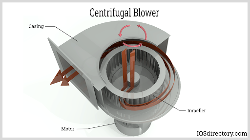
The design of centrifugal blowers includes a motor fan wheel and a housing. The above design is the blower Fig 32. Performance reliability and cost-effectiveness are.
The principles involved in the design of a blower is similar to that of acentrifugal pump except for the fact that the term centrifugal pump is often associated with liquid as its working fluid. In 1826 Guido Bellfrom England invented the centrifugal blower. The centrifugal fan uses the centrifugal power generated from the rotation of impellers to increase the pressure of airgases.
Lobes or impellers rotate in four positions during operation. Volute and casing design The centrifugal fan is surrounding by a volute which along with the sidewalls form a part of the casing. Classical fan and blower basic spiral casing design is based on a free vortex flow pattern and the assumption of a circumferentially uniform flow at the operating point where the.
Cover of the centrifugal blower IV. The main parts of centrifugal blowers are inlet fan volute. Centrifugal blowers are widely used in different industrial applications because of their suitability in any practical circumstance.
Hp 52 kW and the brake horsepower is 10 b. When the impellers rotate the gas near the impellers is. The volute along with cowling used in the vehicle has a.
This paper presents design of. Ad Robust Efficient Easy To Maintain Blowers For Many Applications. And a separate blower system with 5 HP motor fitted at one end of the plant.
All of which have individual benefits volume pressure speed power efficiency etc but all of them will shift. Using standard techniques such as Eulers method Run Fig 31.
2

Schematic Diagram Of The Test Centrifugal Blower Download Scientific Diagram

Pdf Design Calculation Of Single Stage Radial Type Centrifugal Blower For Rice Mill Semantic Scholar

Centrifugal Fan An Overview Sciencedirect Topics
Centrifugal Blowers What Is It How Does It Work Types

Impeller Cross Section In The Blower Volute S Casing Showing The Download Scientific Diagram

Pdf Design Of 5 Kw Radial Type Centrifugal Blower Casing Semantic Scholar
2
0 comments
Post a Comment